1.Introduction
Power inductor is common energy storage passive component, which plays a role in filtering, boosting, and stepping-down in the design of switched-mode power supply. When selecting inductors for step-down switching power supplies, it is necessary to determine maximum input voltage, output voltage, power switching frequency, maximum ripple current, and duty cycle.
2.Function of a power inductor in a buck convertor
In a step-down convertor, one pin of an inductor is connected to Vout. The other pin is connected to the input voltage or GND through switching. Among DC/DC converters, the non-isolated buck switching regulator comprises two topologies: nonsynchronous rectifying (diode) type and synchronous rectifying type.
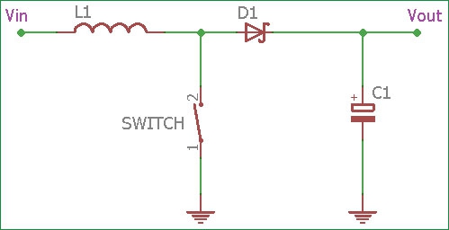
Figure 1. Step-down converter
In-state 1, one pin of the inductor is connected to the input voltage, and the other pin is connected to the output voltage. For a buck converter, the input voltage must be higher than the output voltage, so a forward voltage drop is formed on the inductor.
In-state 2, one pin of the inductor is originally connected to the input voltage, and the other pin is connected to the ground. For a buck converter, its output voltage must be positive, so a negative voltage drop will be formed on the inductor.
Overview of the two topologies and illustrate how they operate.
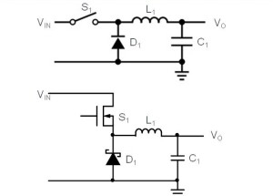
Figure 2. Nonsynchrous(diode) rectifying type
In nonsynchrous(diode) rectifying type, when S1 is turned on, no current flows to D1(off). When S1 is off, a forward current flows to D1(on). In an actual circuit, S1 comprises a transistor, and D1 is a schottky diode. Inefficiency, the nonsynchronous rectifying type trails the synchronous type but the circuit is relatively simple.
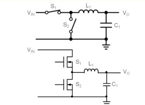
Figure 3. Synchronous rectifying type
In synchronous rectifying type, when S1 is turned on, S2 is turned off. When S1 is off, S2 is turned on. Although the current path is the same as that in the nonsynchronous type, the switches are turned on or off by the control circuit. In an actual circuit, a transistor is used for switching. Although offering higher efficiency, the synchronous rectifying type requires special provisions to boost its efficiency when being subjected to low load. Compared with the nonsynchronouos type, the synchronous type has more complex circuitry.
3.Current calculation through a power inductor in a switch-mode power supply
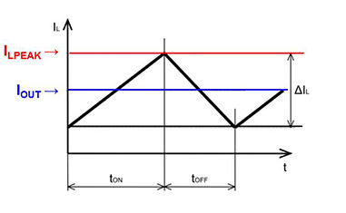
Figure 4. Current curve through an inductor in switch-mode power supply
As we know, V=L(dI/dt).
Therefore, in state 1, the current on the inductor will increase; in state 2, the current on the inductor will decrease. From figure 4 above, we can see that the maximum current flowing through the inductor is the DC current plus half of the peak-to-peak current of the switch which is also called ripple current. According to the below formula, we can calculate the peak current. Among them, a ton is the time of state 1, t is the switching period.
Synchronous converter circuit:

Nonsynchronous convertor circuit:

Rs is the resistance of the core resistance plus the resistance of the winding resistance. Vf is the forward voltage drop of the Schottky diode. R is Rs plus MOSFET on-resistance, R=Rs+Rm.
Saturation current(Isat) is defined at the current point where the inductance drops by 20% or 30%. Definitions in the range of 20-30% are common, but it should be noted some inductor catalogs may use figures of 50% inductance drop. This increases the current shown in the datasheet but may be misleading as far as the usable range of current is concerned. An increase of the saturation current typically means using a larger size component or selecting a smaller inductance value in the same size if we did not change the core materials.
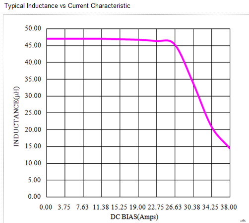
Figure 5. Saturation current curve
We can know why in all converters, the inductance value range (△L≤20% or 30%) under the DC output current is specified, and why is there in the inductance specification book? Parameters too. Because changes of the ripple current will not seriously affect the inductance if the inductor is not saturated. In all applications, it is desirable that the ripple current can be as small as possible, for it will impact the ripple of the output voltage. This is why we sometimes care about the attenuation of the inductance under the DC output current and ignore the inductance under the ripple current in specifications.
4.Inductance calculation of a power inductor in switch mode power supply
When analyzing the working condition of an inductor in the circuit, the following characteristics must be considered:
1. When a current I flows in an inductor L, the energy stored in the inductor is: E=0.5×L×I2 (1)
2. In a switching cycle, the relationship between the change of the inductor current (peak-to-peak ripple current) and the voltage across the inductor is V=(L×di)/dt (2) . It can be seen that the ripple current is related to the inductance value.
3. An inductor also has voltage charging and discharging processes. As long as the inductor voltage changes, the current rate of change di/dt will also be changed; the forward voltage will cause the current to rise linearly, and the reverse voltage will cause the current to drop linearly.
The following describes the calculation of the inductance value of the step-down switching power supply.
First, assume that the switching frequency is 300kHz, the input voltage range is 12V±10%, the output voltage is 5V, Vd is 0.3V, operation current is 1A, and the maximum ripple current is 300mA. The maximum input voltage is 13.2V, and the corresponding duty cycle is:
D=Vo/Vi=5/13.2=0.379 (3)
Among them, Vo is the output voltage and Vi is the output voltage. When the switch is turned on, the voltage on the inductor is:
V=Vi-Vo=13.2-5=8.2V (4)
When the switch is turned off, the voltage on the inductor is:
V=-Vo - Vd=-5.3V (5)
dt=D/F (6)
Substituting formula 2/3/6 into formula 2 gives:

In the calculation of the inductance value of the step-up switching power supply, the calculation method is the same as that of the step-down switching power supply except that the relationship between the duty cycle and the inductor voltage has been changed. Assuming that the switching frequency is 300kHz, the input voltage range is 5V±10%, the output current is 500mA, and the efficiency is 80%, the maximum ripple current is 450mA, and the corresponding duty cycle is: D=1-Vi/Vo=1-5.5 /12=0.542 (7)
Please note that the step-up power supply is different from the step-down power supply in that the load current of the former is not always provided by the inductor current. When the switch is turned on, the inductor current flows into the ground through the switching, and the load current is provided by the output capacitor. Therefore, the output capacitor must have a large enough energy storage capacity to provide the current required by the load during this period. But during the switch-off period, the current flowing through the inductor not only provides the load but also charges the output capacitor.
Generally speaking, the larger the inductance value, the smaller the output ripple. The dynamic response of the power supply will be worse correspondingly, so the selection of the inductance value can be adjusted according to the specific application requirements of the circuit to achieve the most ideal effect. The increase of the switching frequency can make the inductance value smaller, thereby making the physical size of the inductance smaller and saving circuit board space. Therefore, the current switching power supply has a trend of high frequency development to meet the requirements of smaller and smaller electronic products.
5.Conclusion
The inductor is a commonly used component in switching power supplies. Because of its different current and voltage phases, theoretically, the loss is zero. The inductor is often an energy storage element, which has the characteristic of 'coming, rejecting and leaving'. It is often used along with capacitors in input filter and output filter circuits to make the current smooth.
In the switch-mode converter, it is necessary to ensure that an inductor is not in a saturated state to ensure high-efficiency energy storage and transmission. The saturated inductor is equivalent to a direct DC path in the circuit, so energy cannot be stored, which will make the entire design of the switch-mode converter fall short. When the switching frequency of the converter has been determined, the inductor that cooperates with it must be large enough and cannot be saturated.
The inductance in the switching power supply is determined by the switching frequency, input voltage, output voltage, and circuit design. When switching frequency is low, the open and close times are relatively long, in order to keep output uninterrupted needs, the inductance value needs to be increased to store more energy. At the same time, since each switch is relatively long, the energy replenishment is not as quick as the convertor with a high switching frequency, so the current will be relatively small.
In conclusion, a perfect inductor selection requires a good understanding of inductor performance, such as mechanical size, loss, Rdc, Isat, Irms, and withstand voltage. In-circuit performance engineers would like to have usually related to the information available in supplier datasheets.